| gain: |
|---|
 |
| intermodulation: |
|---|
 |
| output impedance: |
|---|
 |
| Layout 112 mm x 53 mm: |
|---|
 |
[begin][Anfang]
high sensitive active antenna 10 kHz - 120 MHz
This antenna is constructed to optimize the sensitivity by choosing the max. signal to noise relation.
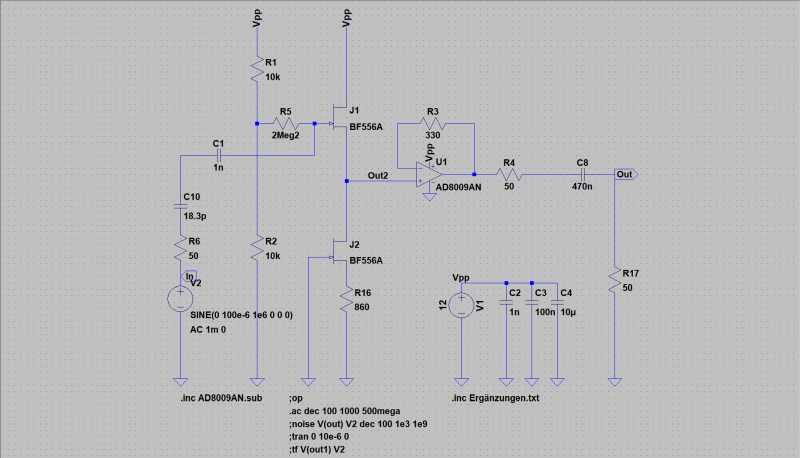
The electronic circuit can be devided in 2 parts. Input-amplification and power-amplification. Input is an
n-channel-FET with FET current source. The power amplifier is an AD8009AN from Analog Devices. The passive antenna is a ground-plane
with a high capacitive beam (150 mm) and a resonance-wavelenght of 2.5 m (120 MHz).
| Specifications: |
|---|
 bandwidth: 10 kHz - 120 MHz bandwidth: 10 kHz - 120 MHz
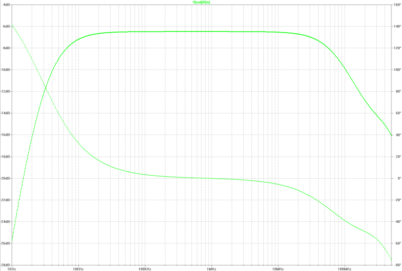
electronical amplification: -6.1 dB
equiv. input-noise voltage: 7.7 nV/SQRT(Hz) @ 1 MHz
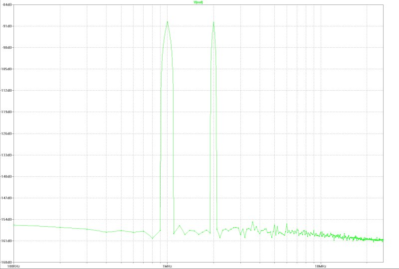
intermodulation 2. order (ui~100 uV, 1 MHz / 2 MHz): -70 dB
max. EMF rms: 2.3 V/m
power: 12 V / 16 mA
output resistance: 50 Ohm
dimensions: 2220 mm x 1050 mm
|
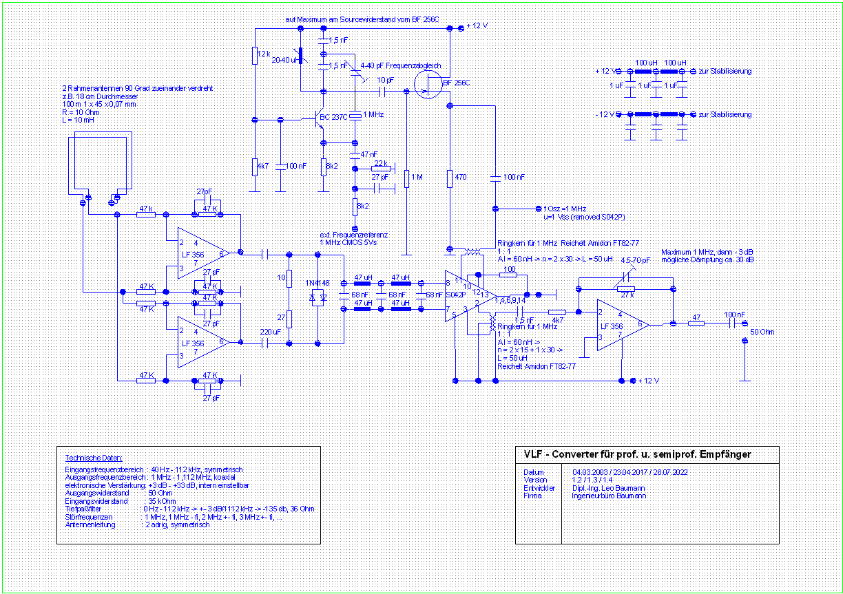
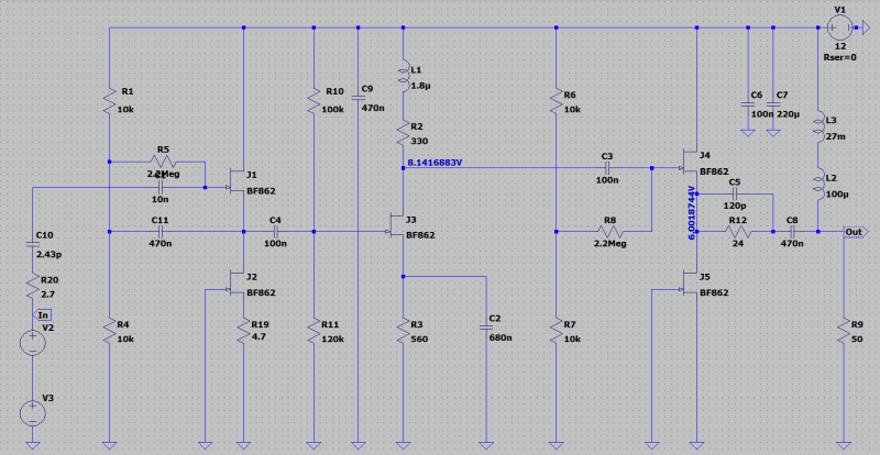
| circuit diagram: |
|---|
 |
| gain: |
|---|
 |
| intermodulation: |
|---|
 |
[begin][home]
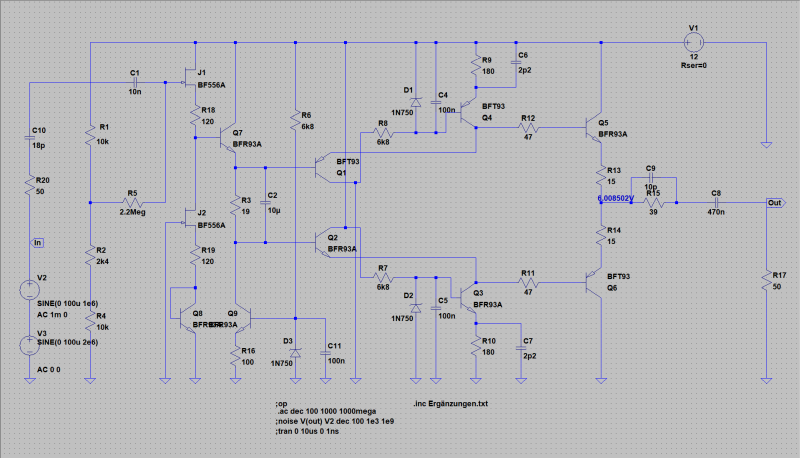
high sensitive active antenna 10 kHz - 530 MHz
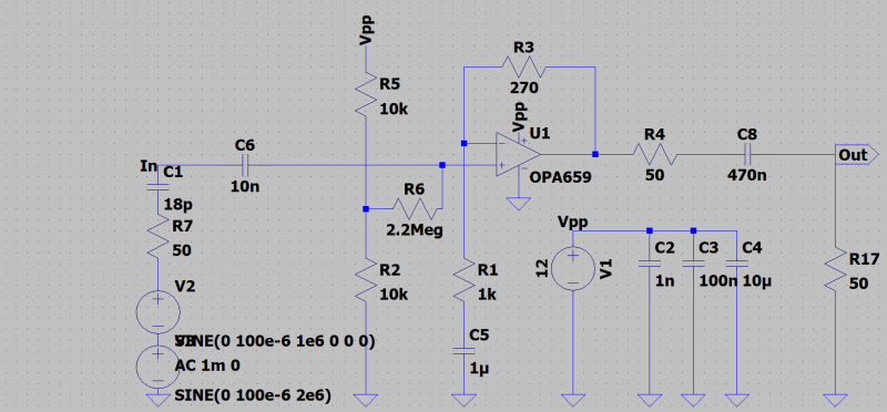
This antenna is constructed to optimize the sensitivity by choosing the max. signal to noise relation. Used is a one stage JFET operational amplifier with an
amplification of 14.8 dB that is more common for far-field usage of transmitting antennas. The OPA659 is a high impedance input amplifier with
all inputs saved with diodes.
| Specifications: |
|---|
bandwidth: 10 kHz - 530 MHz
electronical amplification: -4 dB
equiv. input-noise voltage: 8.8 nV/SQRT(Hz) @ 1 MHz
intermodulation 2. order (ui~100 uV, 1 MHz / 2 MHz): -78 dB
max. EMF rms: 11.6 V/m
power: 12 V / 30 mA
output resistance: 50 Ohm
dimensions: 2220 mm x 1050 mm
|
| circuit diagram: |
|---|
 |
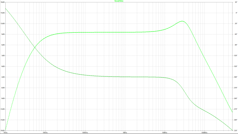
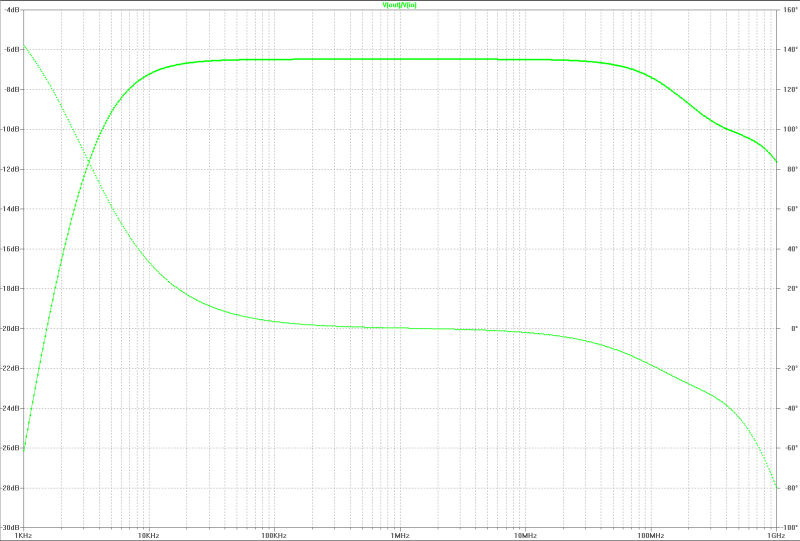
| gain: |
|---|
 |
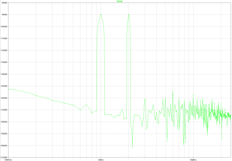
| intermodulation: |
|---|
 |
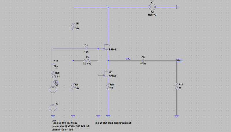
[begin][home]
sensitive active MOS antenna 10 kHz - 120 MHz
This antenna is constructed to optimize the sensitivity by choosing the max. signal to noise relation.
The electronic circuit is reduced to one dual gate MOS-transistor, a BF908 by NXP. This is possible because of the increased
transfer admittance of the transistor, which can adjusted so, that the output impedance ist exactly 50 Ohms. Noise and intermodulation
are better than of the AA120-antenna.
| circuit diagram: |
|---|
 |
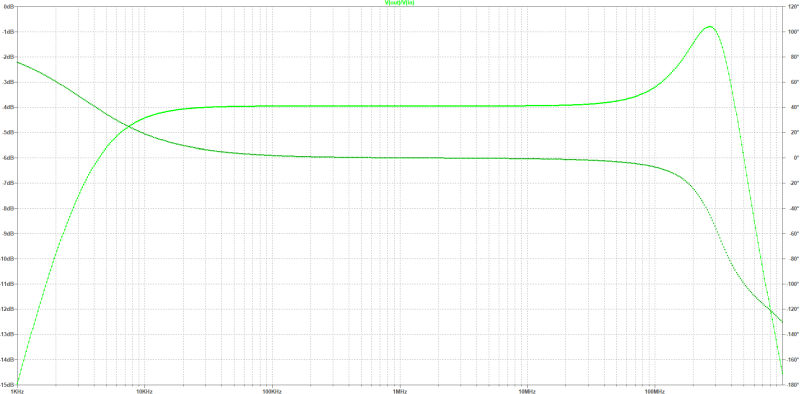
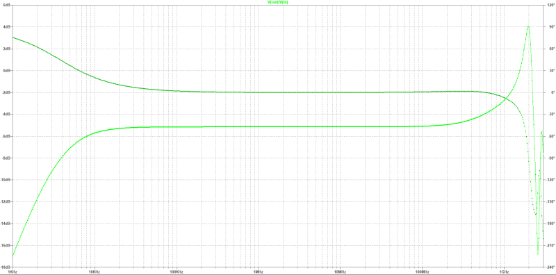
| gain: |
|---|
 |
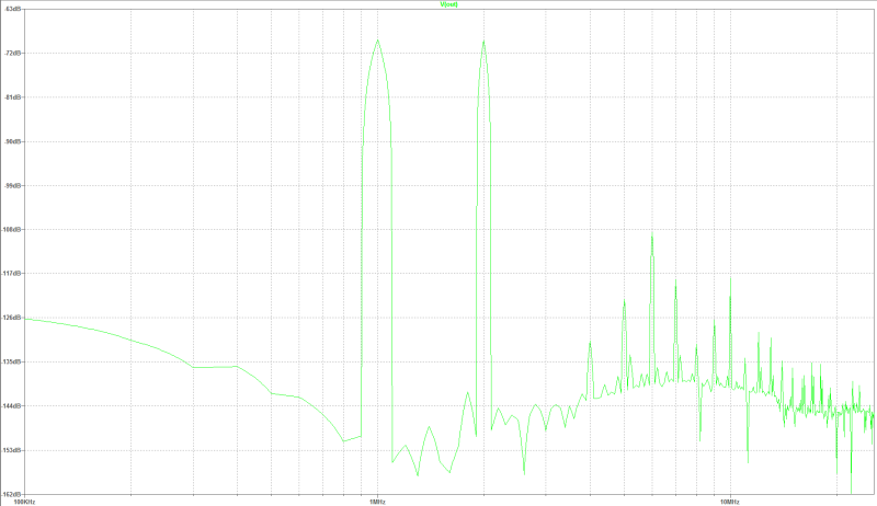
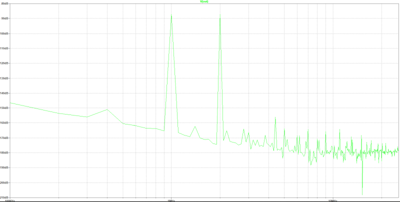
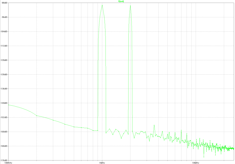
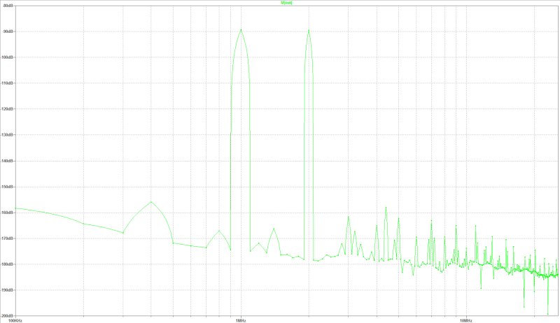
| intermodulation: |
|---|
 |
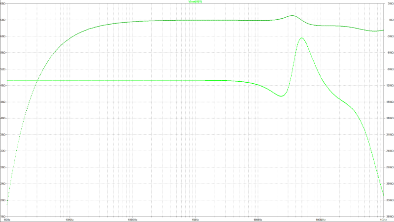
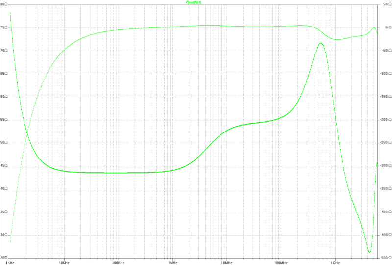
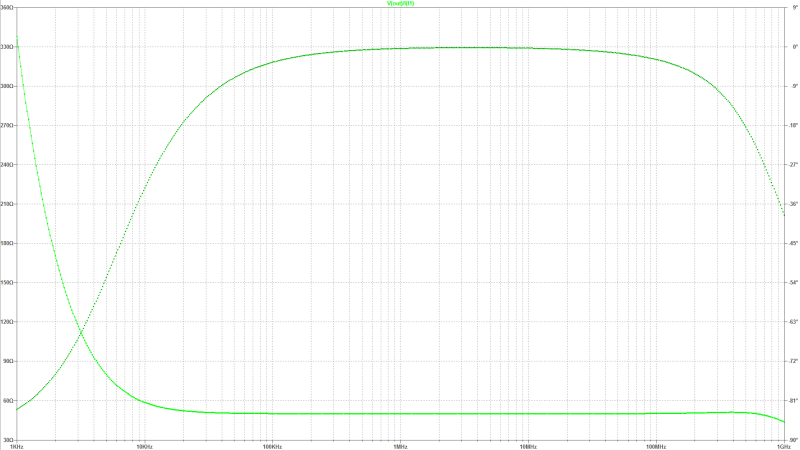
| output impedance: |
|---|
 |
[begin][home]
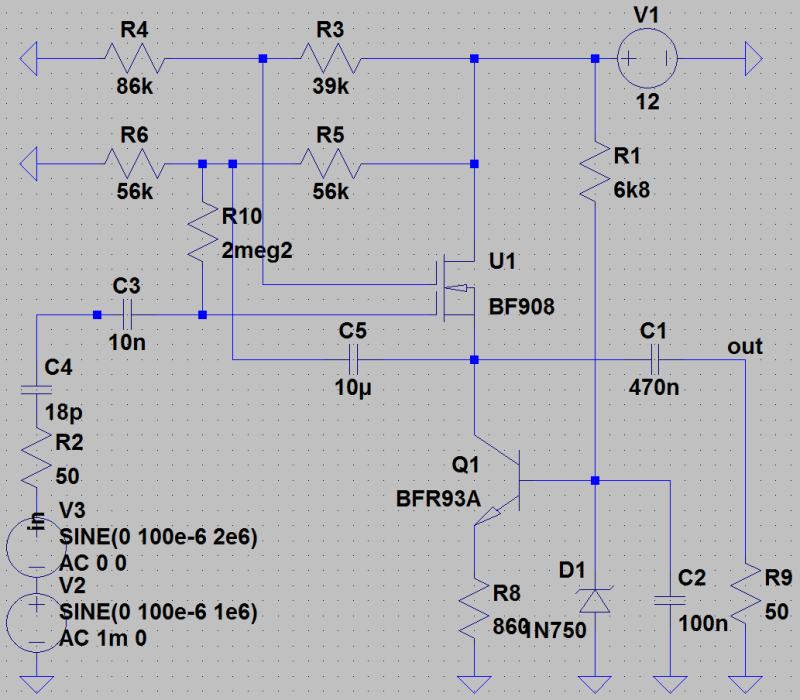
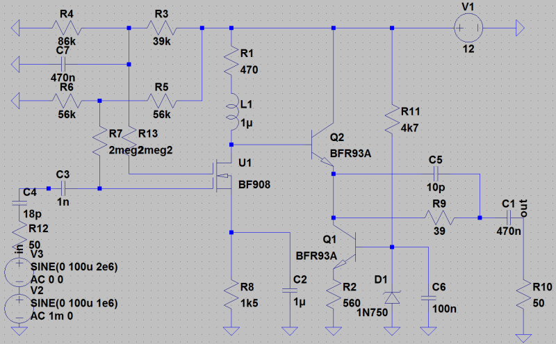
sensitive active MOS antenna with gain
This antenna is constructed to optimize the sensitivity by choosing the max. signal to noise relation.
The electronic circuit is reduced to one dual gate MOS-transistor, a BF908 by NXP and a collector stage. This amplifier is for nonsensitive receivers
with high noise figur. R4 can be designed as a 39 kOhm fixed resistor and 50 kOhm potentiometer and the gain set
over 25 dB.
| Specifications: |
|---|
bandwidth: 10 kHz - 120 MHz
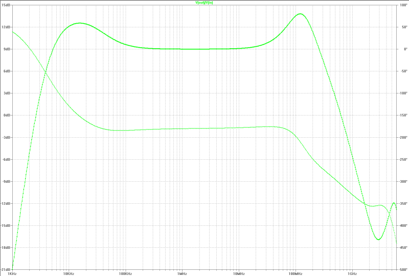
elektronical amplification: 9 - 14 dB
equiv. input-noise voltage: 1.8 nV/SQRT(Hz) @ 1 MHz
max. EMF rms: 0.25 V/m
intermodulation 2. order (ui~100 uV, 1 MHz, 2 MHz): -70 dB
power: 11 mA at 14-25 V over power-supply 230 V
output resistance: 50 Ohm
dimensions: 870 mm x 80 mm
|
| circuit diagram: |
|---|
 |
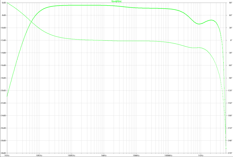
| gain: |
|---|
 |
| intermodulation: |
|---|
 |
| output impedance: |
|---|
 |
[begin][home]
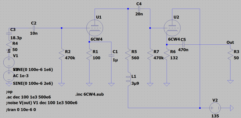
sensitive tube-active-antenna
This antenna is constructed to optimize the sensitivity by choosing the max. signal to noise relation.
Because of the tubes (cascode-circuit, 6CW4) the operation in direct enviroment of transmitters is possible. This antenna is EMP-safe.
Noise-matching can be astablished until about 150 MHz. This circuit is transformerless because a plate-base stage with 50 Ohm impedance
is the output.
| Specifications: |
|---|
| bandwidth: 10 kHz - 150 MHz
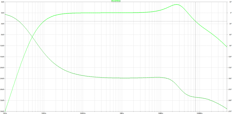
electronical amplification: 0 dB
equiv. input-noise voltage: 2.19 nV/SQRT(Hz) @ 1 MHz
max. EMF rms: > 20 Veff./m
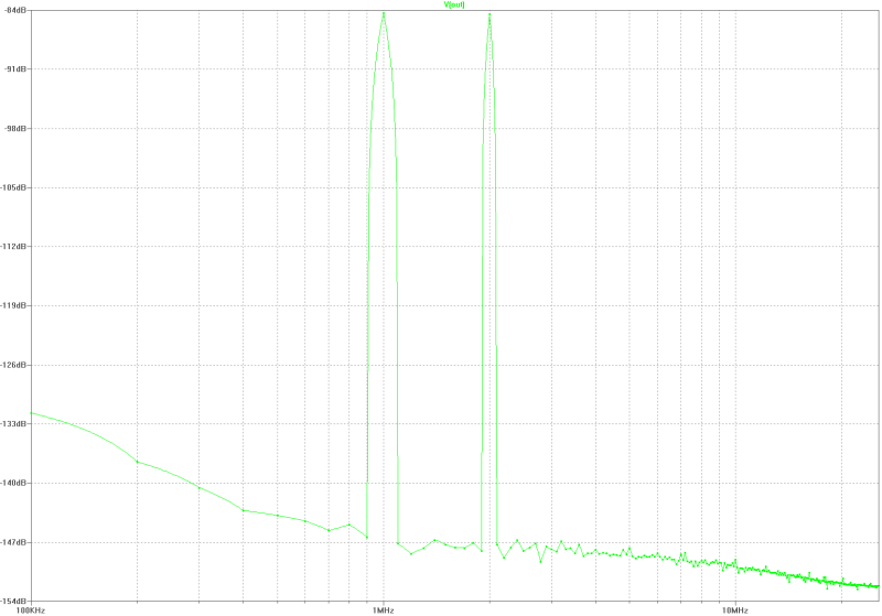
intermodulation 2. order (ui~100uV, 1 MHz, 2 MHz): -63 dB
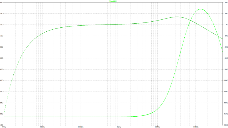
outpur resistance: 50 Ohm
|
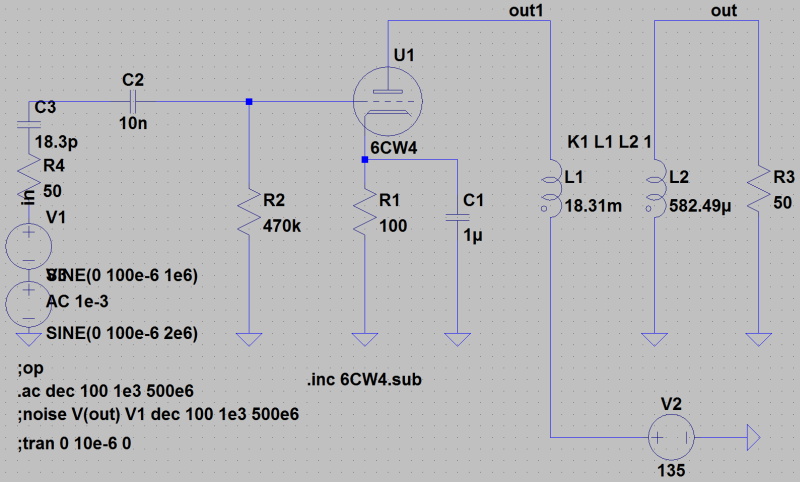
| circuit diagram: |
|---|
 |
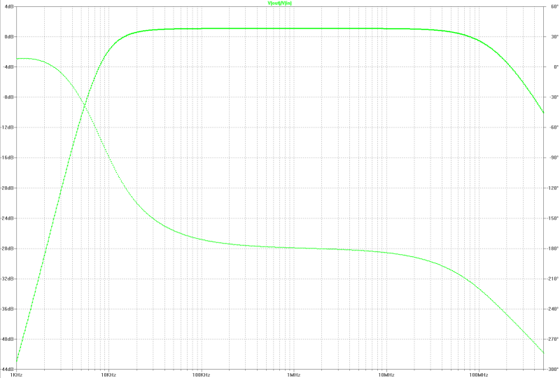
| gain: |
|---|
 |
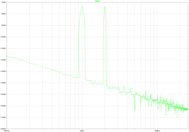
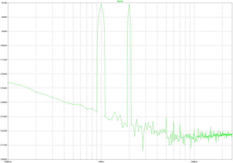
| intermodulation: |
|---|
 |
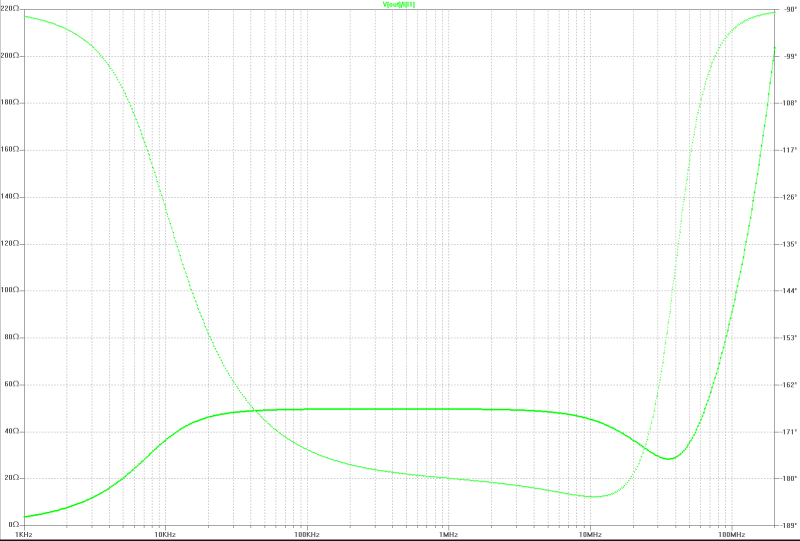
| output impedance: |
|---|
 |
[begin][home]
sensitive tube-active-antenna
This antenna is constructed to optimize the sensitivity by choosing the max. signal to noise relation.
Because of the tube (cathode-base-circuit, 6CW4) the operation in direct enviroment of transmitters is possible.
This antenna is EMP-safe. Noise-matching can be astablished until about 78 MHz. This circuit is transformerless because a plate-base stage
with 50 Ohm impedance is the output.
| Specifications: |
|---|
bandwidth: 10 kHz - 78 MHz
electronical amplification: 0 dB
equiv. input-noise voltage: 2.2 nV/SQRT(Hz) @ 1 MHz
max. EMF rms: > 20 Veff./m
intermodulation 2. order (ui~100uV, 1 MHz, 2 MHz): -67 dB
outpur resistance: 50 Ohm
|
| circuit diagram: |
|---|
 |
| gain: |
|---|
 |
| intermodulation: |
|---|
 |
| output impedance: |
|---|
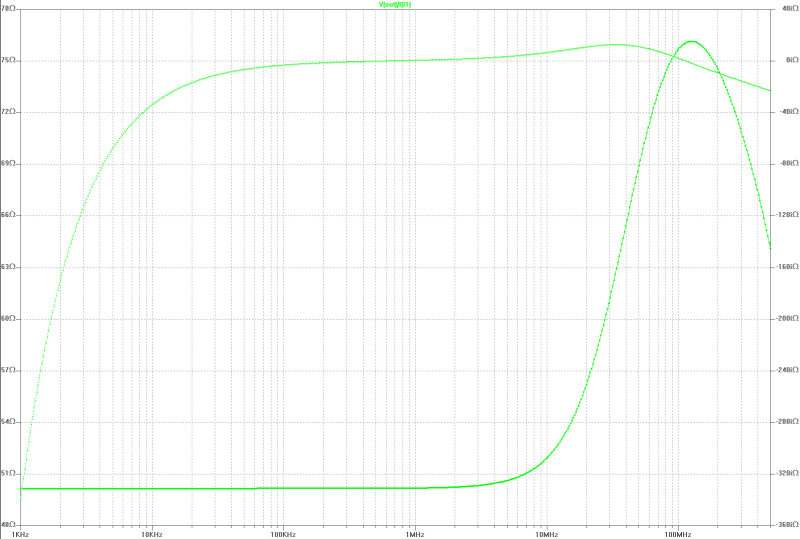 |
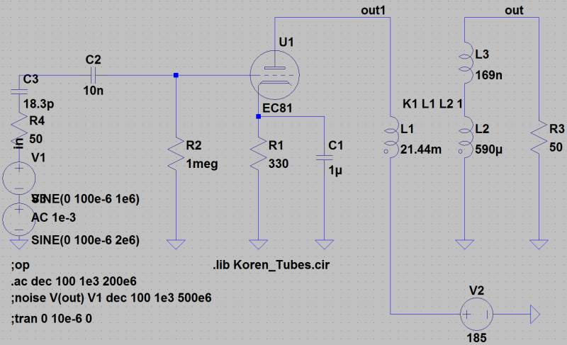
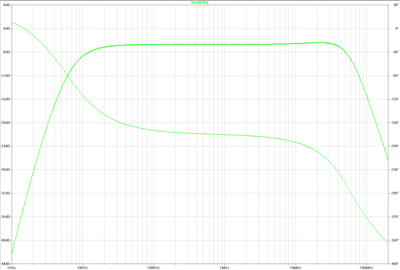
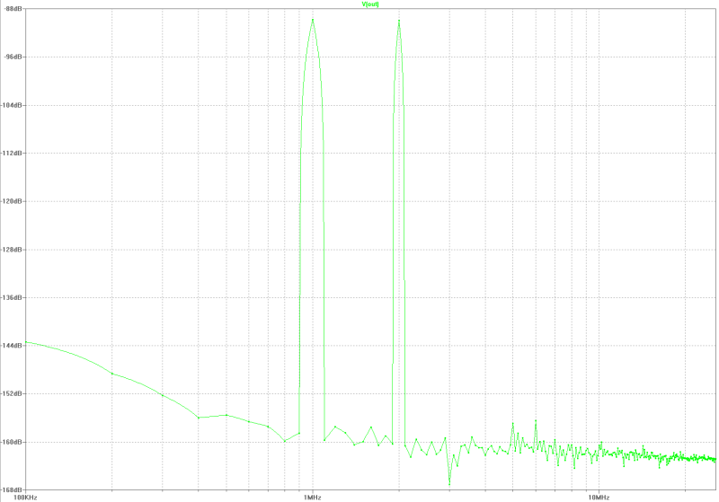
[begin][home]
sensitive tube-active-antenna
This antenna is constructed to optimize the sensitivity by choosing the max. signal to noise relation.
Because of the tube (cathode-base-circuit, EC81) the operation in direct enviroment of transmitters is possible.
This antenna is EMP-safe.Noise-matching can be astablished until about 30 MHz.
Calculations for the transformer [here].
| Specifications: |
|---|
bandwidth: 10 kHz - 70 MHz
electronical amplification: -1.42 dB
equiv. input-noise voltage: 1.9 nV/SQRT(Hz) @ 1 MHz
max. EMF rms: > 20 Veff./m
intermodulation 2. order (ui~100uV, 1 MHz, 2 MHz): -68 dB
outpur resistance: 50 Ohm
|
| circuit diagram: |
|---|
 |
| gain: |
|---|
 |
| intermodulation: |
|---|
 |
| output impedance: |
|---|
 |
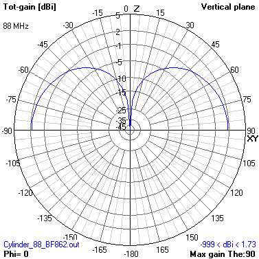
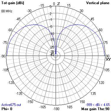
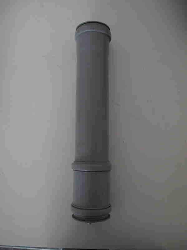
[begin][home]
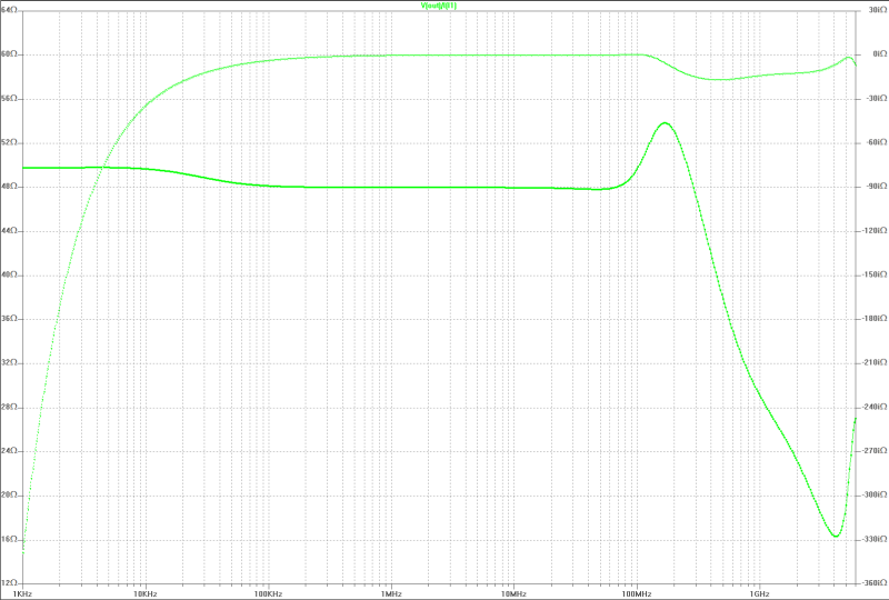
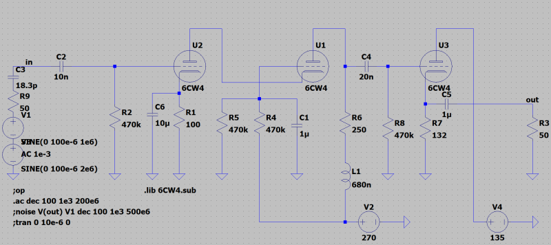
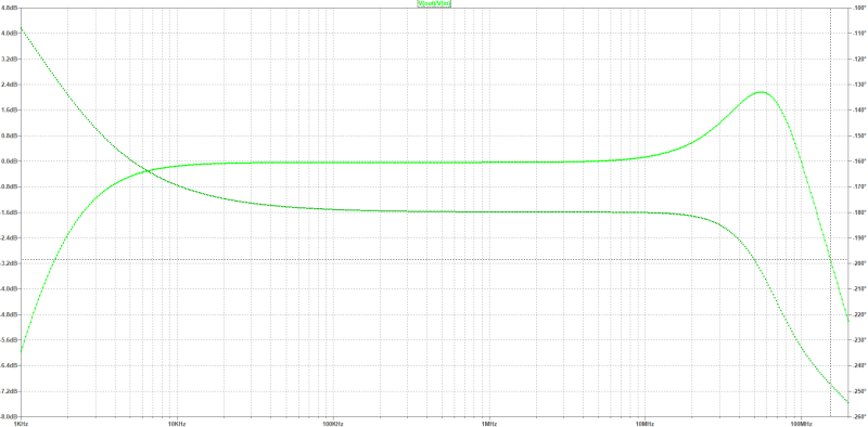
sensitive tube-active-antenna
This antenna is constructed to optimize the sensitivity by choosing the max. signal to noise relation.
Because of the tube (cathode-base-circuit, 6CW4) the operation in direct enviroment of transmitters is possible. This antenna
is EMP-safe. Noise-matching can be astablished until about 100 MHz. The calculation of an passive antenna for this electronic causes
a lenght of 47 cm by a diameter of 150 mm.
Calculations for the transformer [here].
Calculation of the lenght of a passive vertical antenna for this [here].
| Specifications: |
|---|
bandwidth: 10 kHz - 120 MHz
electronical amplification: +1.11 dB
equiv. input-noise voltage: 1.6 nV/SQRT(Hz) @ 1 MHz
max. EMF rms: > 20 Veff./m
intermodulation 2. order (ui~100uV, 1 MHz, 2 MHz): -74 dB
outpur resistance: 50 Ohm
|
| circuit diagram: |
|---|
 |
| gain: |
|---|
 |
| intermodulation: |
|---|
 |
| output impedance: |
|---|
 |
[begin][home]
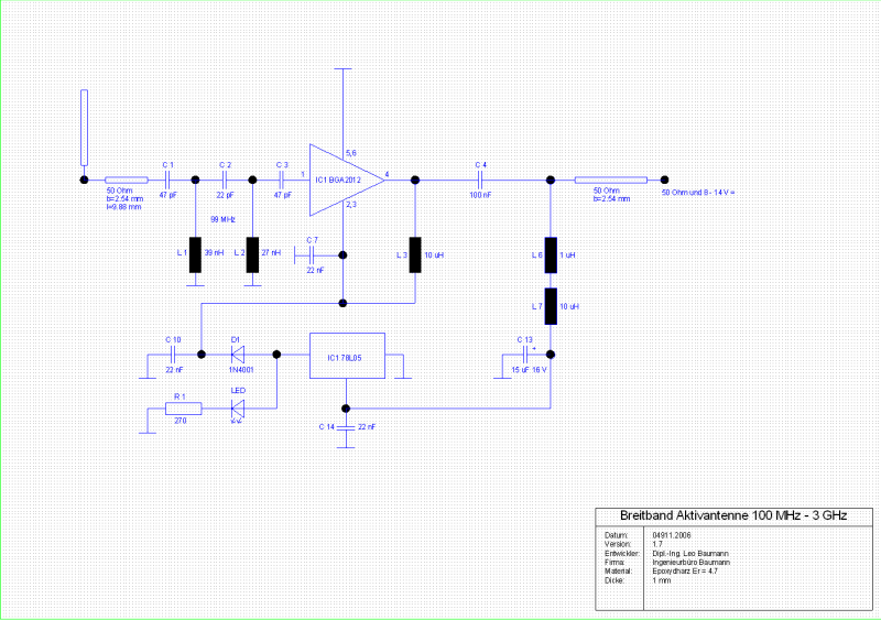
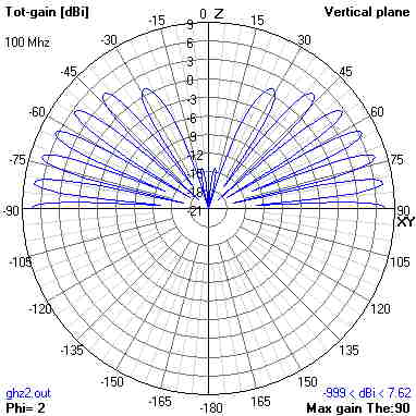
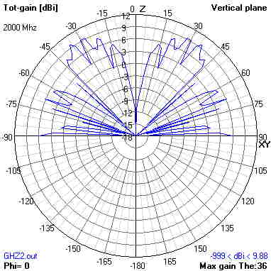
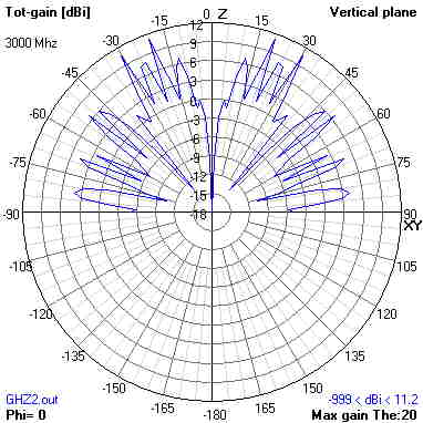
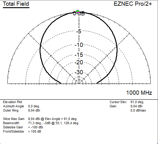
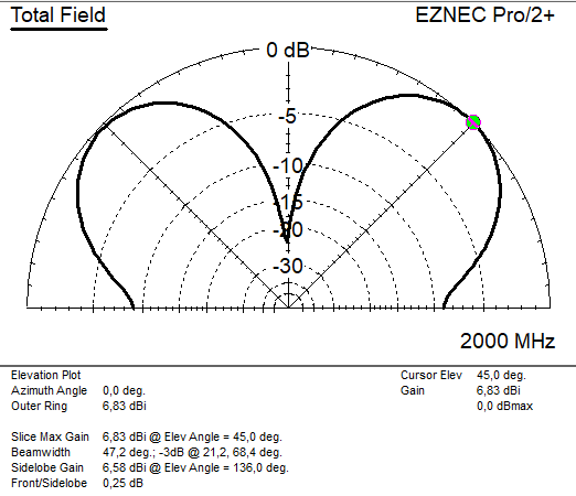
active vertical wideband-antenna 100 MHz - 2 GHz
Wideband antenna with very low noise. The passive antenna-part is matched to the electronic, a MMIC type BGA 2012 from Philips, by a micro-strip-line.
Some computations for this antenna You find [here].
<
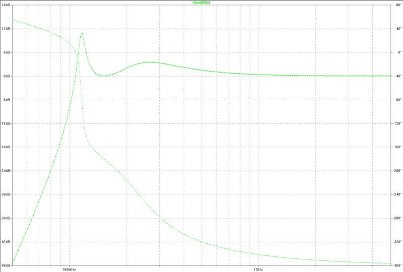
| circuit diagram: |
|---|
 |
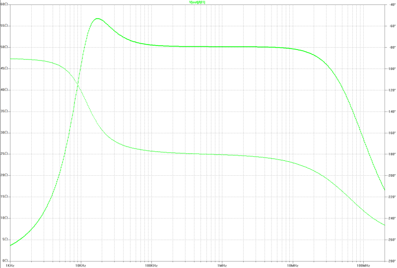
| filter: |
|---|
 |
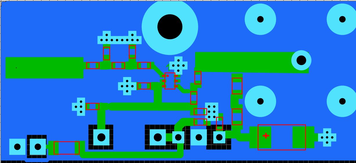
| Layout 20 mm x 44 mm with transmission line: |
|---|
 |
[begin][home]
active hor. Quad wideband-antenne 100 MHz - 2 GHz
Wideband antenna with very low noise. The passive quad-antenna-part is matched to the electronic, a MMIC type BGA 2012 from Philips, by a micro-strip-line.
Some computations for this antenna You find [here].
| circuit diagramm: |
|---|
|
| filter: |
|---|
|
| Layout 20 mm x 44 mm: |
|---|
|
[begin][home]
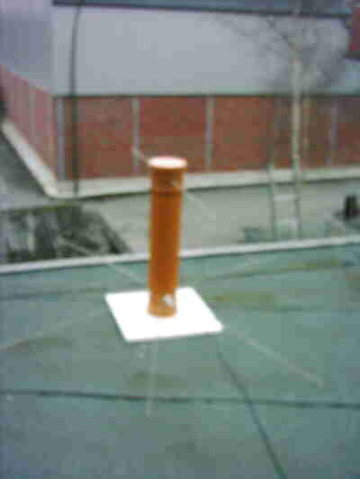
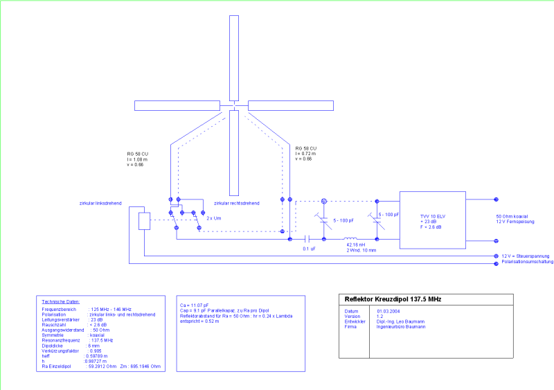
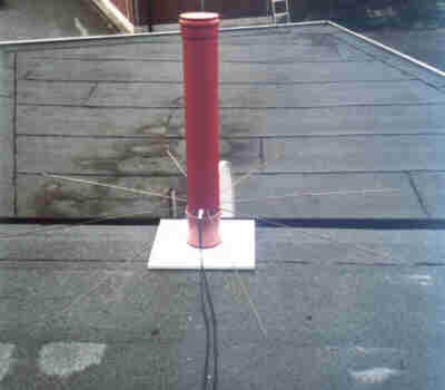
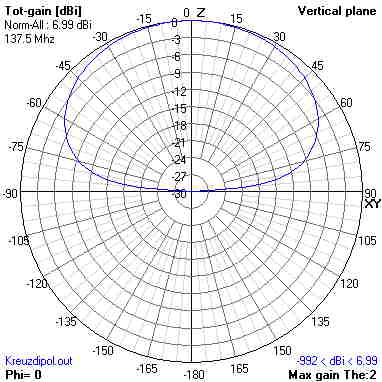
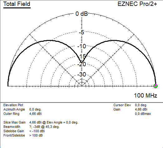
cross-dipol antenna for 137.5 MHz
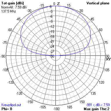
This antenna was build to receive weather-satellites at 137.5 MHz and the 2 m-band.The antenna-height over the radials is choosen, that the gain in the antenna-diagram
is improved for little and low elevation. The max. gain is 7.6 dBi. The dipols are so connectet over transmissen lines, that cirular left or right polarized waves can be
received, it must be switched. A low noise amplifier is added to match the lines to 50 ohms.
| Specifications: |
|---|
 | bandwidth: 132 MHz - 146 MHz
electronical amplification: 20 dB
noise: 2 dB
antenna-gain: 7.6 dBi
current: 45 mA bei 12 V
impedance: 50 Ohm
dimensions: 1000 mm x 600 mm
|
 |
| a view at the circuit diagram: |
|---|
 |
[begin][home]
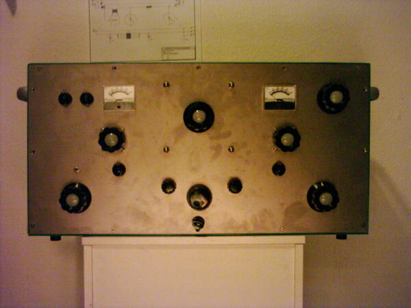
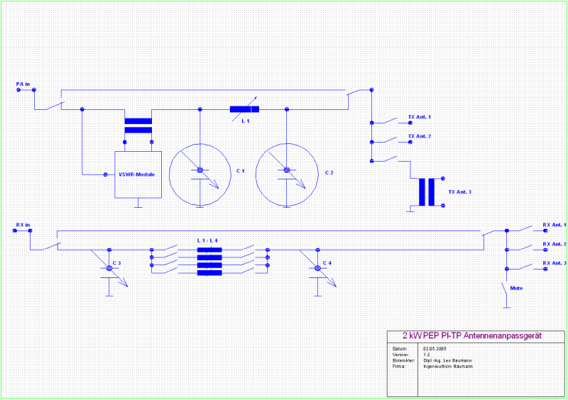
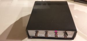
500 W RMS Matchbox in Duplex-PI-Circuit:
With 2 vacuum-Cs up to 42 A and an aircooled roller-inductor from 1.5 MHz to 60 MHz to antennas from 5 Ohms to 500 Ohms. Also, there is the possibility to match RX-antennas with
impedances from 5 Ohms to 2000 Ohms independent from the TX-antenna.
| Specifications: |
|---|
 | frequency-area: 1.5 MHz - 60 MHz
input impedance: 50 Ohms
max. power 500 Wrms
duplex matching
RX-Collins 5 Ohm to 2000 Ohms
TX-Collins 5 Ohm to 500 Ohms
power: 230 V~ 50 Hz
dimensions (B/H/T): 760 mm x 345 mm x 320 mm
weight: 28 Kg
|
| a view at the circuit: |
|---|
 |
[begin][home]
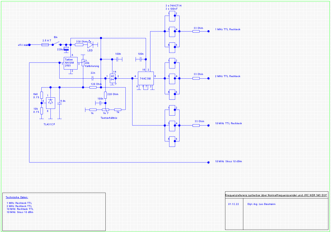
reference frequency generator
The frequency reference works with a 10 MHz OCXO and can be calibrated and adjusted e.g. via a GNSSDO. In practice, however, the Taitien OCXO in long-term usage is more accurate than 0.1 ppb,
as measurements have shown. The specifications below are taken from the data sheet.
| Specifications: |
|---|
 | output 1: 1 MHz TTL Square
output 2: 2 MHz TTL Square
output 3: 10 MHz TTL Square
output 4: 10 MHz Sine 10 dBm
frequency stability: 3 ppb
initial accuracy: 100 ppb after 15 minutes turn on power
1 ppb after 45 minutes
power: 5 V = power supply 2.5 A
|
| view at the circuit: |
|---|
 |
[begin][home]
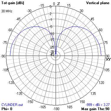
![[here].](Zylinderstruktur.png)
![[here].](Zylinderstruktur1.png)