 fast or as low noise designed class-A MOS-FET-PAfast or as low noise designed MOS-FET-PA with 150 W rms in class AB operationlow noise preamptube-sound with triode in signal path
| development: |
|---|
| fast or as low noise designed class-A MOS-FET-PA |
| fast or as low noise designed MOS-FET-PA with 150 W rms in class AB operation |
| low noise preamp |
| tube-sound with triode in signal path |
To drive Power-MOS-FETs without current do not exploid the possibilities of a MOS-FET. Upper critical frequency and turn-on time will be affected by the manner the MOS-FETs are driven. High-frequency circuitry is asked. We have developed a circuit, which can drive the gate capacity of the FET with more current. The driver is a combination of base-collector coupling with bipolar transistors, a current-source, which can drive fast up to 1/4 Amps. Have a look at the gate-current-schema. The fast MOS-FET-PA has to be compensated a little bit more for square-puls-operation as shown and needs 10 Ohm gate resistances to avoid gate current swinging.
It is possible to design this PA for minimum noise high-end version.
Literature: Halbleiterschaltungstechnik - Tieze/Schenk, Analoge Schaltungen - Seifart, Elektronik - Müseler/Schneider, The Art of Electronics - Horowitz/Hill
| specifications with gate-current driver: | specifications without gate-current driver: | high-end version: |
|---|---|---|
|
|
|
| fast MOS-FET-PA | simple MOS-FET-PA |
|---|---|
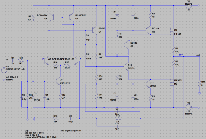 |  |
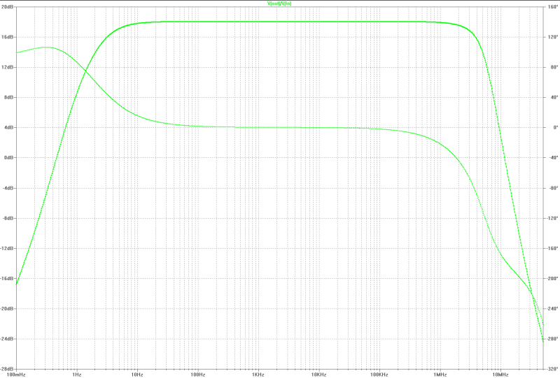
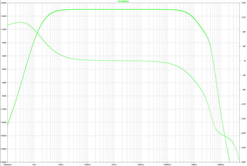
| small signal gain: | small signal gain: |
|---|---|
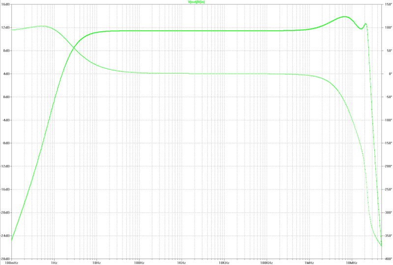 |  |
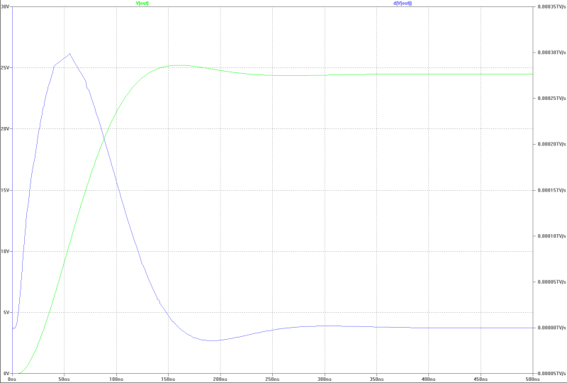
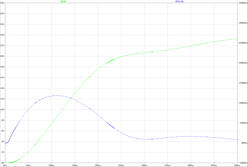
| slew-rate at full power with a jump: | slew-rate at full power with a jump: |
|---|---|
 |  |
| transient overshoot: | transient overshoot: |
|---|---|
 |  |
| gate-current of both MOS-FETs at a full power jump: | gate-current at a full power jump: |
|---|---|
 |  |
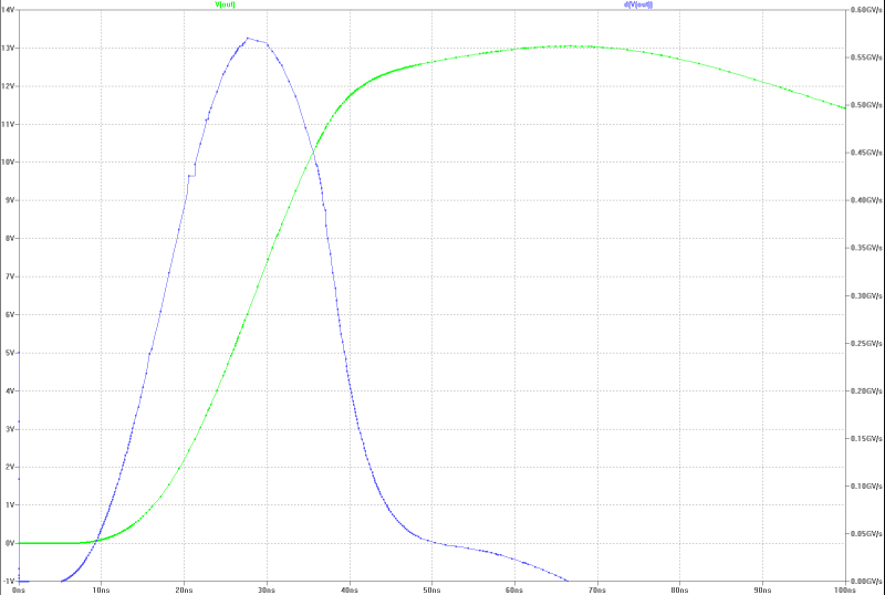
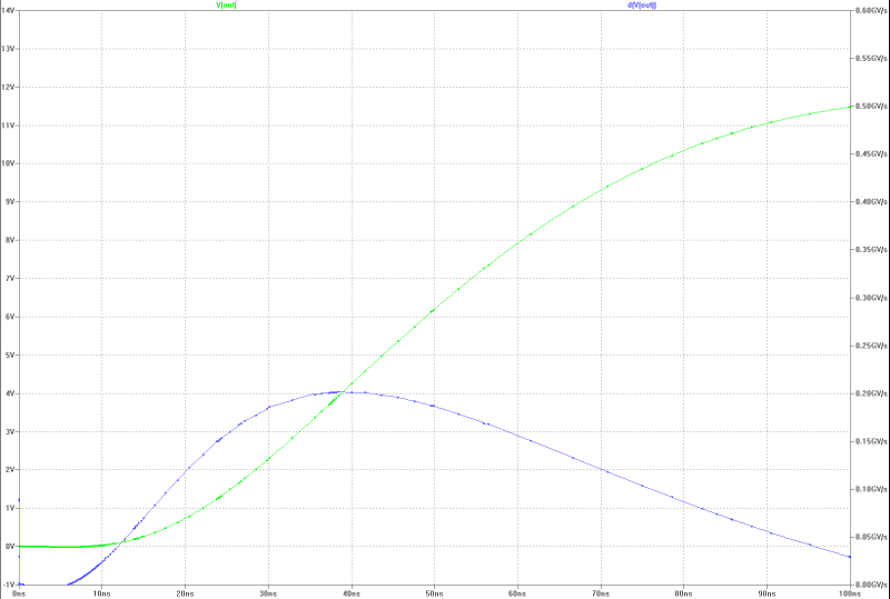
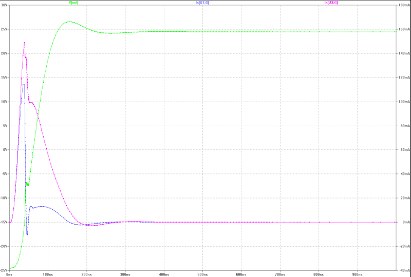
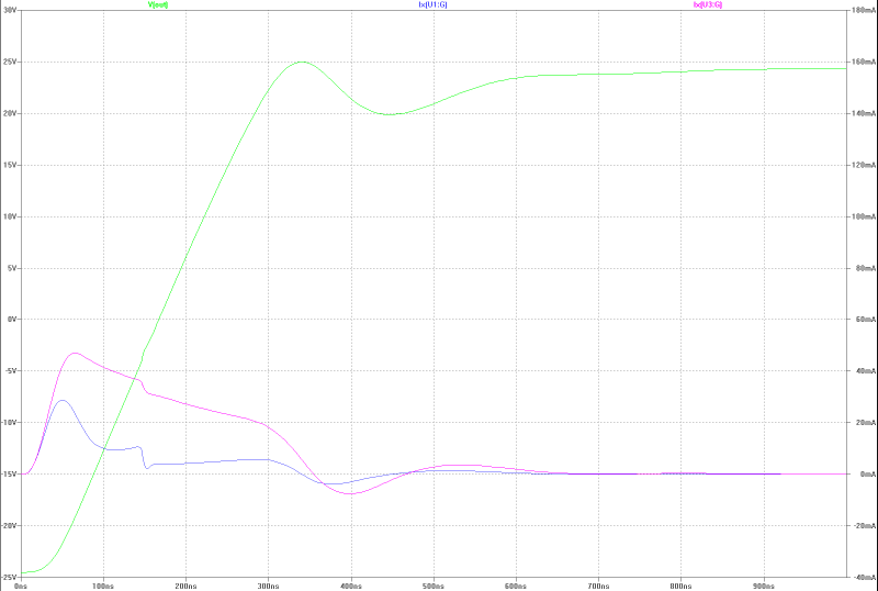
| slew-rate, transient overshoot and gate current of the MOS-FETs at 13 Wrms square-pulse-operation: | slew-rate, transient overshoot and gate current of the MOS-FETs at 13 Wrms square-pulse-operation: |
|---|---|
 |  |
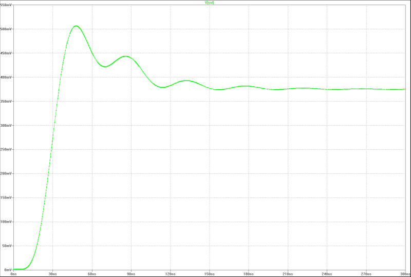
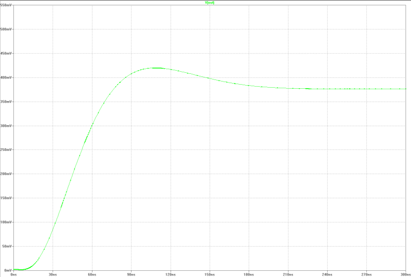
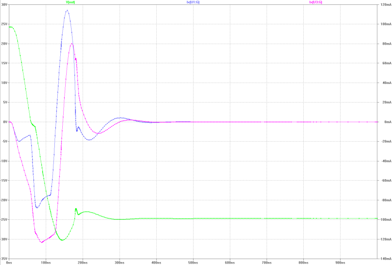
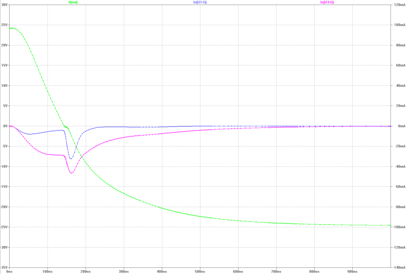
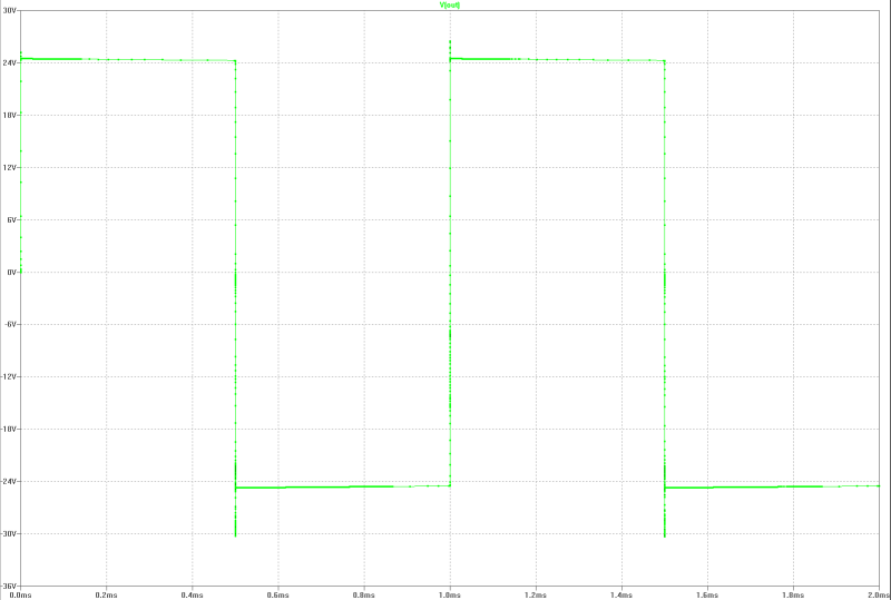
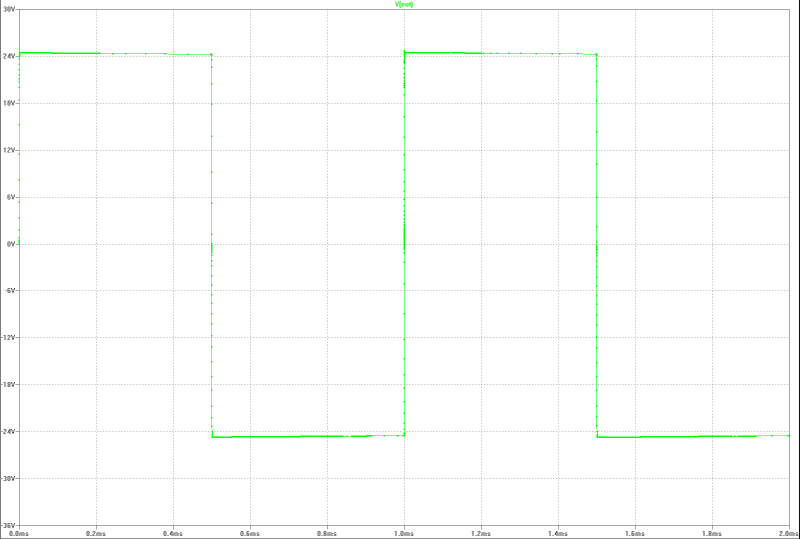
| output at 13 Wrms square-pulse-operation (compensated): | output at 13 Wrms square-pulse-operation: |
|---|---|
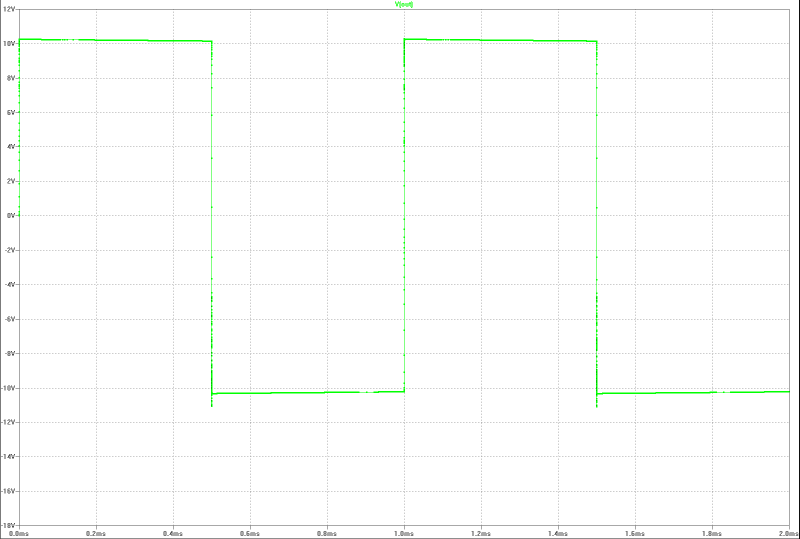 | 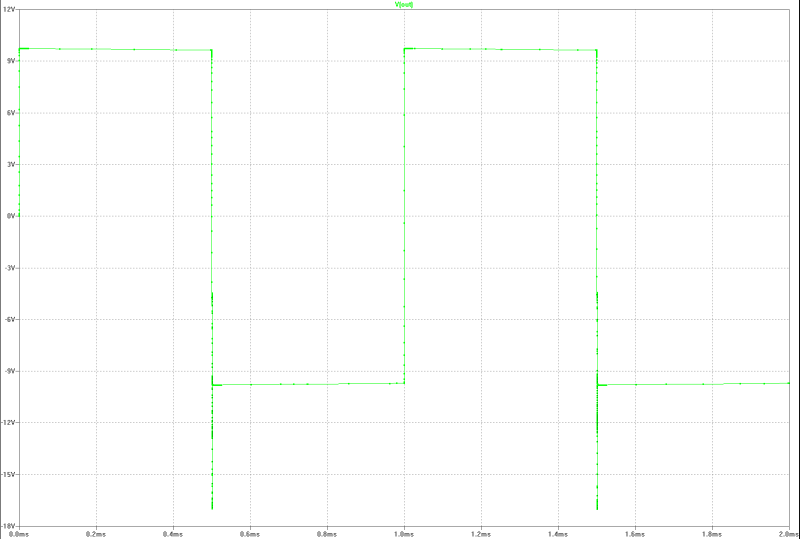 |
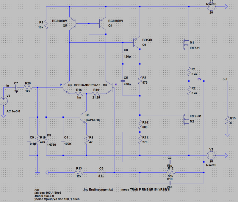
High-End-MOS-FET-PA with 150 W rms in class AB-operation
MOS-FET-PA in 150 W-Class-AB with Gate-Current-Driver for optimal square-pulse-operation. The compensation is adjusted for an transient overshoot of 3 %. Here two different versions. The differences are the quietness current of the differential amplifier and the compensation.
| specifications fast version: | specifications high end version: |
|---|---|
|
|
| fast MOS-FET-PA | high-end MOS-FET-PA |
|---|---|
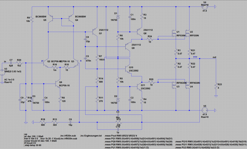 | 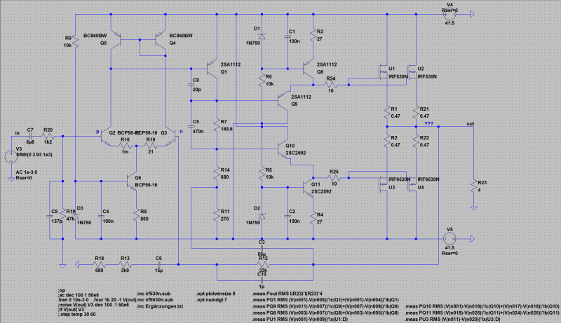 |
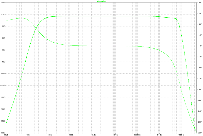
| small signal gain: | small signal gain: |
|---|---|
 |  |
| slew-rate at full power with a jump: | slew-rate at full power with a jump: |
|---|---|
 |  |
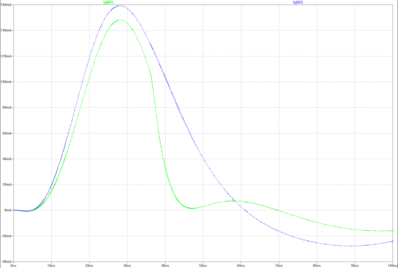
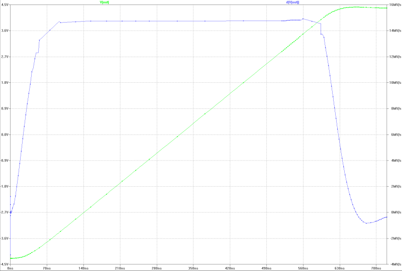
| slew-rate, transient overshoot and gate current of the MOS-FETs at 150 Wrms square-pulse-operation: | slew-rate, transient overshoot and gate current of the MOS-FETs at 150 Wrms square-pulse-operation: |
|---|---|
 |  |
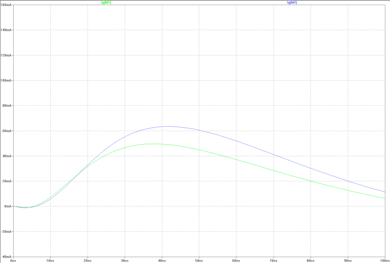
| slew-rate, transient overshoot and gate current of the MOS-FETs at 150 Wrms square-pulse-operation: | slew-rate, transient overshoot and gate current of the MOS-FETs at 150 Wrms square-pulse-operation: |
|---|---|
 |  |
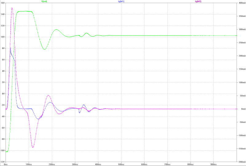
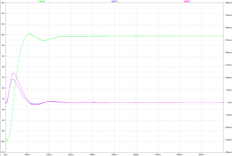
| output at 150 Wrms square-pulse-operation: | output at 150 Wrms square-pulse-operation: |
|---|---|
 |  |
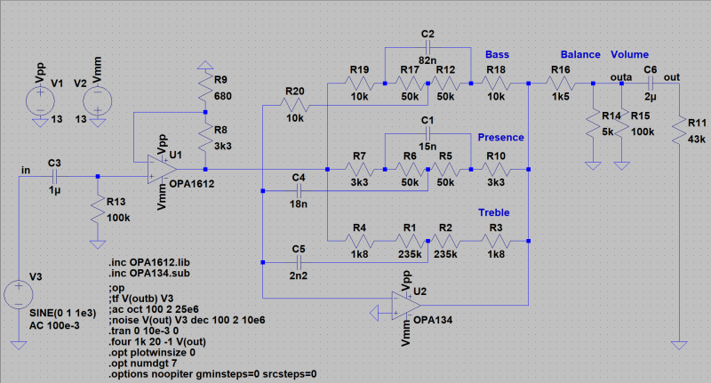
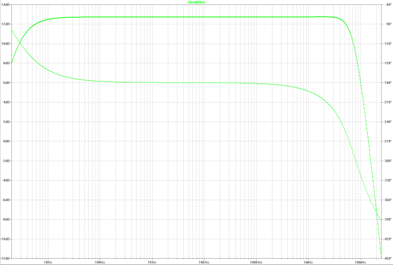
Low noise Preamp with operational amplifiers OPA1612 and OPA134 from Texas Instruments. The adjustment range for treble, presence and bass are about +/- 15 dB. The necessary gain is in the first stage to reduce noise. The degenerative feedback was designed with low impedance because of noise.
| specifications: |
|---|
|
| Preamp: |
|---|
 |
| small signal gain: |
|---|
 |
| full output at 500 kHz: |
|---|
 |
| slew-rate and swing: |
|---|
 |
| harmonic distortion: |
|---|
 |
| equivalent input noise voltage: |
|---|
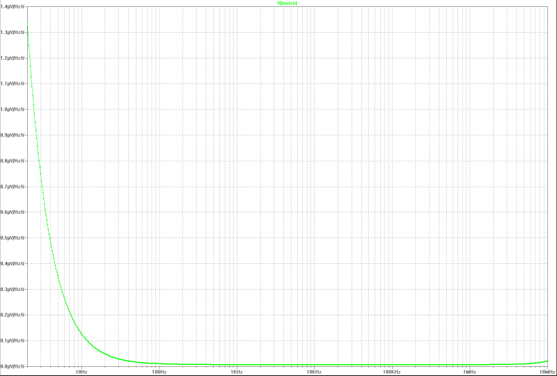 |
typically tubesound with triode and non-linear transformer:
Many music-lover sense the sound of natural sound and Hi-Fi-Solid-State-Amplifiers subjective "cold" and "boring". This device produces the "warm", "interesting" sound of tube amplifiers by a pentode as triode. The tube-sound results from the non-linear characteristik of the tube Ik=kx(Ust)^3/2 and of the non-linear transformer.
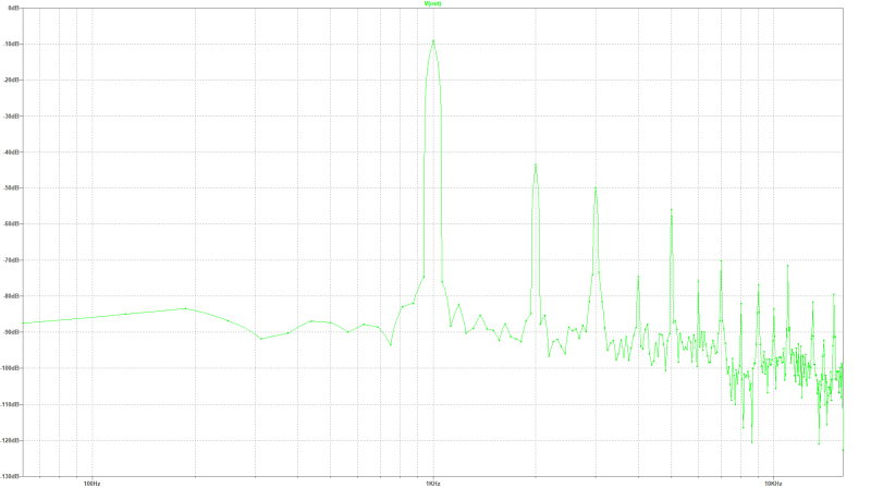
Input- and output voltage is in this design about 500 mVs. disturption adjustment with R6 (saturation degree 0 Ohm to 330 Ohm). With R1 (plate current 180 Ohm + 470 Ohm Poti) the anode alternate current can be adjusted. The very low-noise operational amplifier regulates the saturation degree of the tube. The THD of the 1 kHz-signal is at 2.1 mAss anode alternating current 2.33 %. with this saturation degree of the tube.
Note: A simulation with a mono-wav-file in LTspice has shown that the result is good. [simulation output 1] [simulation output 2]
Thanks to Andreas Fecht and Alexander Bordodynov/Russia, who had some ideas for this.
| specifications: |
|---|
|
| circuit for 1 channel: |
|---|
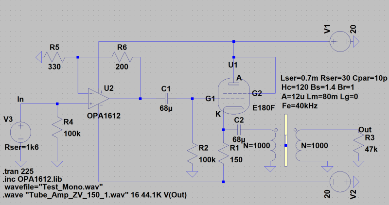 Grid 3 to Kathode |
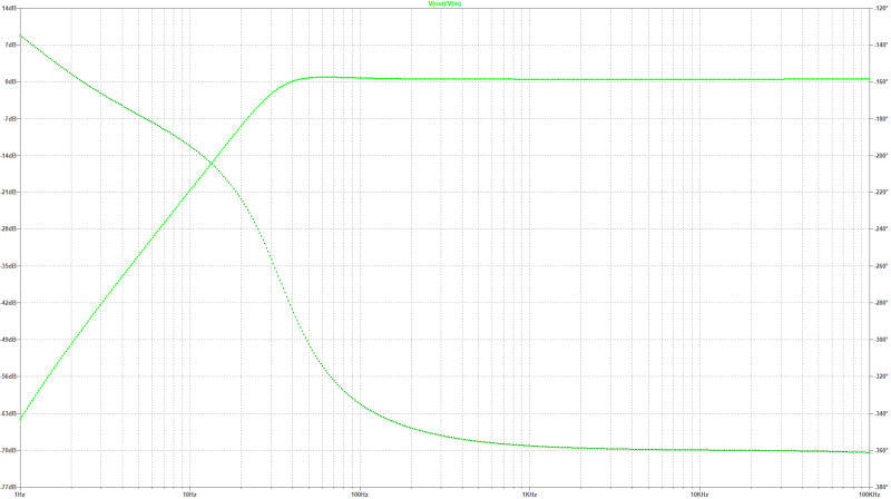
| small signal gain: |
|---|
 |
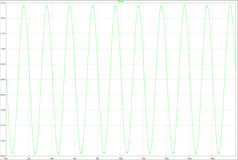
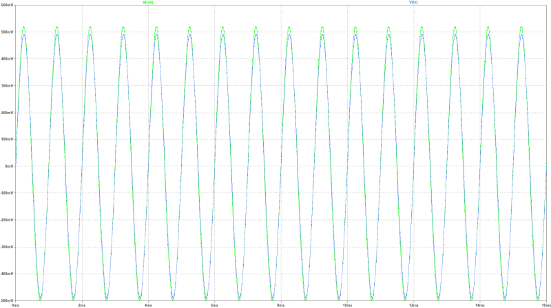
| in- and output signal 1 kHz, moderate adjustment: |
|---|
 |
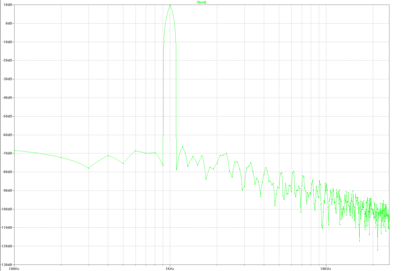
| spectum of the disturbed signal: |
|---|
 |